
Thursday, October 11, 2012
Mau5 Halloween?
Not too long ago, ch00f over at ch00ftech posted some awesome electroluminescent music reactive "Kanye" glasses he built for new years. So when my cousin came to me and asked me to help her design some lights for a Deadmau5 head (mau5head?) Halloween costume, I knew exactly what I wanted to do! Electroluminescent wire around the ears and mouth, and a music reactive VU meter made of more EL wire inside the mouth area. I shamelessly stole borrowed from his analog design, improving on a couple key areas in order to use digital logic to drive the triacs and generate some PWM channels for LEDs. I designed a small (~3"x3") PCB that will fit easily inside the costume head. It uses optoisolated triacs to switch the high voltage EL wire, and uses a capacitor switching IC to generate a negative voltage rail for the op-amps to maximize the resolution I get from the envelope detector circuit since I will be using the ADC to sample the voltage. Sometime this next week I'll etch the board and build it up. More updates soon!

Saturday, September 29, 2012
LED shelves, completed!
Well, after quite a bit of work, I have succeeded in designing, building, programming and installing a completely custom set of liquor shelves for my friends' apartment. I could not be happier with the results. The controller design I came up with works perfectly, and I was able to write code for it that is bug free and fits neatly within the small amount of program memory available in the attiny2313 microcontroller I used. The finished product looks like it would be more at home in a high end bar than an apartment!


Monday, September 24, 2012
More LEDs
I've got another project near completion now, RGB LED underlit color changeable liquor shelves! After visiting the Lazy Dog Cafe that's opened recently nearby and seeing the LED lit shelves at the bar there, my friends decided we needed to build some for their apartment. So, after a visit to Ikea, we returned with three of their "lack" floating wall shelves. I recommended some LED strip from an eBay seller, picked out an appropriate 12v power supply, and set to work designing a controller to select the light color.
I decided that one controller and input device per shelf would simplify the wiring scheme and allow the use of low power microcontrollers. Each shelf will be its own unit, and all we will have to do is chain power from one shelf to the next when they are installed.
I put a lot of thought into how the controller should allow a color to be selected, and after considering potentiometers, rotary encoders, and pushbuttons, I decided that the cleanest way would be to use Atmel's "qtouch" series of capacitive touch sensors to detect the presence of a finger over a copper pad etched on the backside of the control panel. This creates a completely flat, blank front panel for the controller, which shows the positions of the three touch buttons by an LED glowing through the PCB substrate.
I already had some Attiny2313 microcontrollers on hand, so I designed the controller around them. Two buttons on the front change the color of the light by going around the color wheel clockwise or counterclockwise, but this only allows fully saturated colors and not white, so a third button selects white, and if held turns off the lights. A cycling mode can also be entered where the controller cycles around the color wheel by itself, and the arrow buttons instead select the speed at which it does so.
The hollow construction of the shelves will make it easy to hide all wiring and electronics on the interior of the shelves.


New Word Clock
Haven't updated in a while, but I spent quite a bit of the last part of my summer working on a project for my dad. Last Christmas, I built him a word clock following instructions from this instructable for him to keep in his office. He has gotten a lot of comments on it since its been in his office, but particularly from his boss, so my dad asked me to build another one to give to him. This time I decided to make a PCB instead of using perfboard, and made a few small improvements on the design.
Of course, now that my dad was helping build the enclosure for the clock it came out much better than the one I built myself. He has a 3D printer rapid prototyping machine in his office, so rather than building the LED holder out of cardboard and the front panel from transparency sheets, this time he drew up and printed the whole thing. The light dividers and LED holder are all one piece, and the front panel was printed in two layers so that the light can shine through the lower layer of white plastic. I'll post up the .stl files for those parts and the Cadsoft Eagle board files if anyone is interested.


Thursday, July 5, 2012
LED display update
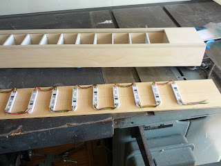
The housing for the display has been made, with a lot of help from my dad, and today I installed the LED strip into it. The light bar is separated into twenty segments by dividers and one LED pixel is installed in each segment. There is a slot in the front to receive a piece of fluorescent light fixture diffuser sheet to make it look nice and clean, and to hide the LEDs and wiring. I'm working on code to make more interesting effects and I think the microphone pre-amp needs higher gain. There will be some arcade style buttons to select different music effects and such when it is finished.


Thursday, June 28, 2012
LED display
As if I needed another project, recently a couple of my friends moved into their first apartment, and I told them I would build something cool to go in the living room. I decided that a music reactive LED light bar would be an awesome idea, and started thinking about the best way to build it. I settled on using a strand of "RGB pixels" from a Chinese seller that use the ws2801 controller. They are basically a strand of small modules that each have a controller and three RGB LEDs, and are all chained together. They use a two wire SPI-like serial interface to allow 24 bit color control for each module. I am going to mount 20 of them into a enclosure with some diffuser on top to make a kind of bargraph display, and control them with a ATMEGA328 microcontroller. In order for the device to be music reactive, I decided a microphone would be easiest, since that way it doesn't need to be wired to the speaker system. Originally I was just going to use an envelope detector circuit to get sound level information, but I decided that to make for more interesting music animations an MSGEQ7 graphic equalizer chip would be best. The datasheet for this chip says that it has 20dB of amplification built in, but that means I still needed an additional 20dB or so to make the microphone signal usable with this chip. I used a rail-to-rail op-amp to accomplish this. The controller now is all built, but I have not yet programmed it and I am still waiting on the led string. I'll update when I have made more progress!


Thursday, June 21, 2012
Dekatron II
I was originally going to use most of those dekatron tubes I ordered to create some sort of clock with the tubes as the display, but I think I am first going to use two of them to create a CPU and RAM usage meter to go into one of the 5.25" bays on the front panel of my PC. The only thing I was unsure of was how to power the tube's supply and communicate with the controller without endangering my computer's sensitive electronics with any sort of high voltage or noise in the event that something goes wrong. I knew I could use opto-isolators on the output of an FTDI usb to UART serial converter to communicate safely, but the best solution I could figure out for power was a separate ac converter. That's when I found these nifty DC-DC isolated supplies at jameco, I can use them to supply power to the dekatron tubes without any direct electrical connection, so that even if something goes wrong my PC will remain safe. And the whole device can be a self contained unit the size of a standard optical drive, without any extra clunky wall warts.
Oscilloscope
Got something cool in the mail today, my first real oscilloscope! Its an Owon SDS7102V digital storage scope, it seems to be the best bang-for-the-buck that I could find anywhere. I ordered it from Saelig electronics, they gave me free shipping and a 5% educational discount. It has the largest, highest resolution display(800x600) and the deepest memory(10M) of any scope in its price class, plus it's thin and portable. The ADC used in this scope is a Chinese clone of a much more expensive chip, but it is actually built for the 1 Gsa/s speed and 100MHz bandwidth whereas typically other scopes in this price range use a combination of lower spec interleaved ADCs to get the job done. I got the optional Li-Ion battery with it as well so I can use it wherever without having to drag out the extension cord. So far I am very happy with it, I am still learning how to use some of the features but I am sure it will come in handy.


Monday, June 18, 2012
UV exposure Unit
Up til now I have been making my own circuit boards at home with the toner transfer method, and while I have had some success it seems very hit and miss, and doesn't get amazing resolution. The toner is porous, doesn't always adhere well, can't be used for very thin traces, and is susceptible to melting and spreading out while being ironed on. I decided to upgrade my PCB making process to one using photo lithography. I bought some dry film photoresist sheets on eBay, but in order to have consistent results an ultraviolet exposure box is necessary. I designed, built and programmed this box, and am very happy with how it turned out, as well as the results I am now able to achieve with it. I used almost 500 UV wide angle LEDs emitting at 395 nm as the light source, and a handful of red LEDs mixed in to allow me to line up the masks and get things set up without prematurely exposing the resist. The power supply and timer/controller is in the box on the right hand side, as well as a lockout magnetic switch to only turn on the UV when it detects the box is closed. The indicator shows when the UV panels are powered on. The time may be easily entered using the keypad on top, and is displayed with four large seven-segment LED displays above the keypad. Buttons A through D allow commonly used times to be stored and recalled as presets using the microcontroller's EEPROM. If the lid is opened while the UV is on, the controller turns it off, turns on the red lights, and pauses the timer until the lid is closed again.


 I've added the CAD files for my original design Here, and I have updated the schematic with the changes I mentioned in the comments, available Here. There's more than one new design for the display board, both use only 3 I/O pins and should drive the display with even brightness. The first one uses four 74hc595 shift registers, and four ULN2003 darlington arrays. If the high current 595 shift register variant is used, the darlington arrays can be omitted. The second version multiplexes the LED displays together, using only two 595 shift registers and one darlington array, and four BC558 PNP BJTs. This design saves quite a few parts, but may be slightly harder to write code for, and may be slightly dimmer due to the multiplexing. Either design should be better than what I have used in my old design, and the control board should also be compatible with the Sparkfun serial seven segment display, if you do not want to bother with building your own.


Dekatrons
Continuing my fascination with surplus soviet electronics, I discovered an interesting type of vacuum tube known as a dekatron. These tubes are a type of decade counter, and were commonly used as an early type of memory or to select among several outputs. They are a type of cold cathode gas discharge tube, and use some rather elegant physics to form high performance counters for the vacuum tube era. Inside the end of a dekatron there are a number of metal electrode pins arranged in circle around a central anode disk. There are ten main cathodes and either two or three guide cathodes between each main cathode, depending on the type of dekatron. Upon being powered, one of the main cathodes will conduct, creating a small amount of plasma to form around the conducting cathode. If the next guide electrode becomes more negative than the conducting cathode, the glow will "jump" from the currently conducting cathode to the next one over. Clever circuitry is connected to the guides so that when a pulse is applied to the counter, it causes the guides to transfer the glow from one main cathode to the next one, and since there are ten main cathodes, this creates a decade counter. "Cathode zero" has an output to create a carry pulse into the next dekatron tube. These devices were able to produce surprisingly high count rates in the megahertz range near the end of their development, but were eventually abandoned. They fell out of use once decade counter integrated circuits became available due to their higher performance, lower cost, and ease of use. However, they are still occasionally used by hobbyists as a type of display due to their interesting looks and retro/vintage feel. These devices are available on eBay, of course, and I purchased a few each of two different types. Modern microcontrollers make these easy to drive; a high voltage BJT transistor is connected to each electrode, and software in the microcontroller makes each electrode the most negative in turn. This enables forward and backward motion, as well as allowing the glow to stop on any of the electrodes, not just the ten main ones. I devised a way to determine when cathode zero is the one conducting using an optocoupler to signal the microcontroller, so that I have a home position to start at when the microcontroller first turns on. My plan for these is to create a module to fit in the 5.25" drive bay of my PC and use two of these tubes to indicate the current CPU and RAM usage. The CPU tube will spin at a faster rate when the CPU is under load, and the RAM tube will show a circular bar graph to represent the percentage of used RAM. This project is not yet finished, but I expect it soon will be as I have started working on it again. So far I have the high voltage supply built and the microcontroller operating one of the tubes, and I have a good amount of the code already written as well. More updates soon.


Geiger Tubes
Geiger counters are a relatively old technology, a common sight and sound in sci-fi films or thrillers, and their parts are commonly available on the surplus market due to soviet stockpiles. Naturally I had to buy a tube to play around with. They are relatively simple devices, a tube is filled with a special low pressure mixture of gases and a high voltage (400 to 900 volts) is applied across two electrodes inside the tube. When ionizing radiation passed through the tube, it triggers a discharge that briefly causes the tube to conduct, causing a detectable current pulse that can be counted by integrator circuitry, and creating the recognizable click sound that most people are familiar with from movies and television. Most tubes are sensitive to beta and gamma radiation, but not alpha since it is so easily stopped and cant make it through the tube's glass or metal walls. some, however are given a thin mica end window to allow the alpha radiation into the tube and allowing it to sense alpha radiation as well. I was able to find one of these mica window tubes on eBay and ordered it from a seller in Ukraine. I also built the high voltage supply for it from the schematic at this website. It used a 555 timer to create a boost converter to create the high voltage, and a hex inverter to create the click sound. I intended to make this into a single handheld unit, with the tube and supply on board, as well as the battery, charger circuitry, microcontroller and both an analog panel meter and digital LCD display to show the current reading. I never finished building the whole thing but I did get the tube and supply working together and took apart a cheap smoke detector to get a alpha radiation test source. Most smoke detectors use an extremely tiny amount of radioactive Americium, a byproduct of maintaining our plutonium based nuclear arsenal. This element is a powerful alpha emitter, and even the tiny amount of it present in the smoke detector is enough to overwhelm the Geiger tube, creating a constant screeching sound instead of a series of discrete clicks. However, as an alpha emitter it is relatively harmless as its radiation is easily stopped by a single piece of paper, your skin, or a few inches of air. It produces no detectable radiation when stored inside a small piece of aluminum foil. I am still interested in completing this project and will likely pick it back up sometime in the near future.


Near IR photography
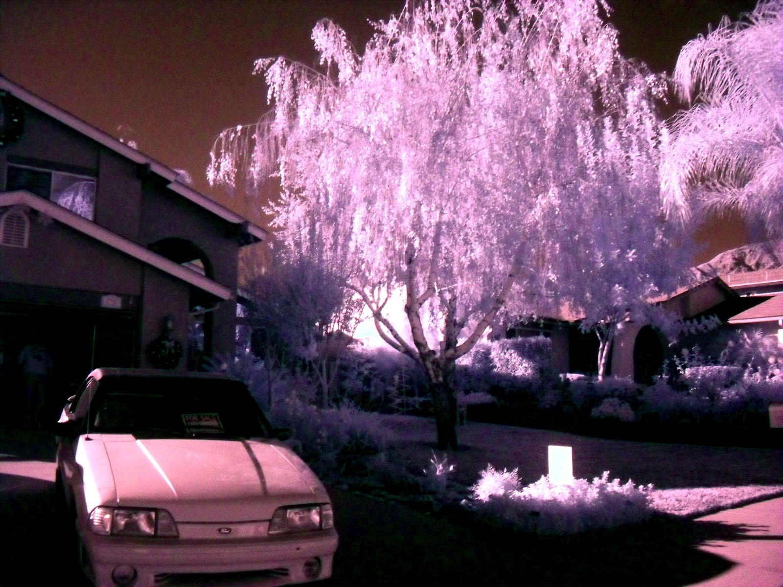
After seeing some near infrared images on the internet I decided making my own near infrared camera might be a fun weekend project. I picked up a semi-broken digital camera on eBay for only 20 dollars, and discovered that the lens extending mechanism was just a little weak. It works fine most of the time, but occasionally I have to help the camera extend its lens a little when turning it on. I disassembled the camera, and removed the IR filter placed over the image sensor, replacing it with a homemade visible light filter made from a couple layers of floppy disc film. This prevents visible light passing through, so that the images recorded are mostly due to IR and near IR light passing through the film. I got pretty good results with this camera, despite the optical path having been changed due to replacing the IR filter with thinner plastic film. Plants reflect light in the Infrared spectrum since it is not usable for photosynthesis, and so they appear white in these photos.


Lazors
This project always seems to impress everyone who sees it, but I am afraid that I can't take much credit for it; I only assembled it using knowledge and parts from the wealth of information and helpful people at laserpointerforums. Relatively recently a well known manufacturer of projectors launched a series of slim projectors that use a diode laser based light source. A block of 24 one or two watt laser diodes in combination with a powerful red LED and green phosphor provide the RGB light source necessary for the projector's operation. These diodes are very robust and powerful, with power output at a level that was previously unattainable by hobbyists. It didn't take long for a cottage industry sprung up around buying and parting out the projectors for the laser diodes, and they are now readily available on eBay and through the forums. Driver modules were also created to handle the larger power requirements for these new diodes, and machinists now sell kits to retrofit the laser diode, collimating lens, and driver module into Chinese LED flashlight housings. This produces a high quality and powerful portable battery operated laser. The prices were reasonable, so I bought the diode and driver and commissioned the creation of the heatsink module, and assembled my very own 1 watt 445nm handheld laser. It can burn most flammable objects, pop balloons, shine onto low clouds, and create a visible glow in the air for miles. Of course I am extremely careful to wear appropriate safety goggles when using it as a single reflection into a persons eye can cause instant blindness.


Ammo box speakers
Last summer I decided I wanted to build a portable stereo speaker box so that I would have something to play music with at the beach. I settled on using a surplus metal ammo can as the enclosure, and picked up a 50 cal can at the local surplus store. I wasn't going to repaint it, but the can I purchased had been rather poorly resprayed at some point so I sanded it down and painted it with some tough paint. I bought a 15w Class D amplifier from Sure Electronics. These amplifiers are small, powerful, extremely efficient(~90%) and above all, cheap. I also purchased a set of 4" automotive speakers. I had some 3s LiPo battery packs on hand already, so I installed the appropriate battery connector on the amplifier. These batteries seem to work great with the amplifier since it operates well at 12 volts, and ceases working just before the batteries reach their minimum charge level(~9v), ensuring they don't become overdischarged. They also give a working time of around 8 hours with a 2200 mah pack, and there is certainly room for a larger battery if longer runtimes are desired. There is also room inside to permanently install a small balance charger if a complete system is desired, but I just take out the batteries and charge them outside. I put in an audio input jack, power switch and a power indicator I salvaged from an old control panel, and the final product is an attractive portable amplifier that has served me well for playing music on the go.


Liquid cooling
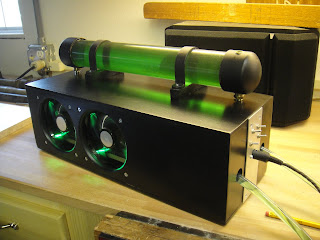
There is something about combining fast computers and liquid cooling systems that I have always found interesting, so back when the Nehalem series of processors were announced, I began saving up so that I would be able to build my own system. Slowly I was able to purchase all the necessary parts, and I assembled the computer. When it was finally together I was out of money for the liquid cooling system. After much though and research, I decided I was going to go old school with my liquid cooling setup, and built it using homemade parts, centered around an automotive heater core. I combined the radiator, fans, water pump, and coolant reservoir into one external unit so that I would be able to use it with future PCs simply by purchasing and connecting an appropriate waterblock. The system kept my processor idling at only several degrees above ambient temperature, and allowed stable overclocks to 4.2Ghz. The toggle switches allow me to switch the fans on each side between on, off, and half speed for quieter operation. I wrote an instructable for this project, available here.


Subscribe to:
Comments (Atom)