Wednesday, November 27, 2013

Wireless SNES controllers

I saw something neat on hackaday a few days ago: wireless SNES controllers!  They use the logic board from a Logitech wireless keyboard. All Logitech wireless devices use the Logitech Unifying receiver now, which is minuscule and can pair with up to six devices at once. I decided it would be awesome to build at least a pair of them for multiplayer Super Nintendo emulator gaming on the living room media center computer. The cheapest keyboard with unifying receiver support I could find turned out to be the Logitech k360, frequently available for less than $20 brand new, but I picked up a refurbished model for $15 on amazon. A smoky smelling but otherwise pristine SNES controller was sourced from eBay, and I set to work stuffing one inside the other!

I'm really happy with the result, the only external modifications are the LED in place of the cord and the slide switch to turn off the controller when not in use. The guy who built the controller featured on hackaday used a model of keyboard that runs on 1.5 volts but I found that mine contains an NRF24LE1 Nordic Semiconductor 2.4GHz radio SOC that needs at least 1.9V to operate. Space is tight inside the controller and the original keyboard is advertised as having 3 year battery life on 2 AA batteries, so I decided to use a 3v CR2032 coin cell battery to power my controller. According to Logitech, the three year life quoted corresponds to 2 million key presses per year, or 6 million total. That's conservatively about 6600 key presses per mAH, so my single coin cell ought to last for about 1.2 million key presses, or thereabouts. That should be plenty for a couple years of occasional use, and the battery is in a holder inside so replacement just requires unscrewing five screws and popping a new battery in. 
I used my meter to trace the membrane switch traces to figure out which two pins to connect for each of twelve keys, then cut traces on the snes controller PCB and wired each button to the appropriate pair of pins. I will make the second controller use a different non-overlapping set of keys since the emulator program can't tell the difference between the same key on two different keyboards. 
The board from the k360 has the key membranes clamped directly to its contacts, which are a very thin copper trace covered with some kind of conductive ink, so soldering wires to them was tricky. After the black ink is cleaned off there's not much copper there to solder to. 
My keyboard also has no power indicator to show that it has been turned on, so i rigged up a simple circuit to flash an LED briefly when when the switch is flipped, to indicate that the battery is not dead and to show which position of the switch is on without having to make any marks on the case. When the switch is moved to the "on" position, current flows through an LED and charges a small capacitor, causing the LED to flash briefly. When the switch is turned off the capacitor discharges through a schottky diode and a resistor.

Thursday, September 26, 2013

Mini CNC build

Got a new toy to tinker with the other day. Its an old Ram Optical microscope system, originally used at my Dad's work for inspecting parts.

They upgraded quite a while ago to a newer system, but aside from the ancient desktop computer that records the measurements, this machine is still in very good shape. My Dad wants to set up the video microscope on the bench with a small LCD monitor, and I plan to use the rest of the machine for a small CNC build.  It should be a perfect platform for a small CNC for milling circuit boards and engraving wood, plastic, and maybe aluminum. the envelope is small, only about 4x8x8" but I rarely need circuit boards larger than 4x8" anyway. The machine is highly accurate since it was meant for taking measurements using the microscope, I just need to come up with a spindle and motor for it that is also accurate enough.

The drivers that were used in this machine are controlled over RS232, either by a computer or directly with the joystick. They are also overkill for the small NEMA 17 stepper motors that drive this machine. I'm sure I could program a microcontroller to move the machine around, but I'm less sure I could easily program it to interpret G code into commands for the controllers. So, I think my best bet is to replace the driver completely, in favor of the TinyG CNC controller. It accepts G code streamed over USB and has the appropriate motor drivers on-board, for simple setup and use. I've already set to work determining the pinout of the DB9 motor connectors on the side of the case, and the wiring scheme of the current control box so that I can easily install the new control board.

Thursday, July 18, 2013

Dekatron PC Status Display

Well, I found a good use for a pair of the soviet made dekatron counting tubes I bought on eBay months ago: a CPU and RAM usage display that fits in one of the 5.25" optical drive bays on my desktop computer.

Regular readers of my blog (if any of you exist) will remember that I bought two kinds of these from an eBay seller in Ukraine about a year ago, some 3-guide argon filled OG-3 tubes and some 2-guide neon filled OG-4 tubes. I found that the OG-4 tubes are much brighter, and glow a pleasant shade of orange, although they count at a  much slower rate than the OG-3s. I ended up etching some circuit boards and building a power supply according to threeneuron's  schematic Here. It worked beautifully, and I was able to play around with controlling the dekatrons from an arduino. 


Several months passed before I came up with the idea to build this PC status display with the dekatrons, several more passed before I had time to actually start on it. I knew that housing a 450 Volt, potentially noisy switching supply inside my computer was risky, but I think the design I came up with should mitigate any potential risks. It is powered through an NSD-10 isolated DC-DC supply, and communications is done with a USB to serial converter that uses opto-isolators to interface with the microcontroller. I designed it around an ATMEGA328 running the arduino bootloader and an FT232RL usb to serial converter, so it is actually fully arduino compatible. Once installed in the computer, reprogramming it is as simple as opening the arduino IDE and selecting the appropriate COM port.


I had the front panel and the dekatron tube mount inside 3D printed, and the whole thing is housed within the shell of an old 5.25" drive. A small python program retrieves the RAM and CPU usage percentages and sends them to the device over serial. The device displays the data by spinning the left dekatron at a rate related to the current CPU load, and the right dekatron shows a bar graph representing the current proportion of RAM used.   
I wasn't totally happy with how the CPU dekatron reacted to abrupt changes in CPU load, so I had the arduino calculate a running average over the last second, so it would speed up and slow down smoothly. I also wanted more of a response to small changes at the bottom end of the scale, while still reaching the maximum spin rate, so I generated a non-linear response in excel and used a lookup table in the arduino to determine how fast to spin the dekatron. 

In the video below I compiled some arduino code first just to show what a mild load on the CPU caused the dekatron display to do, then I started a stress test to show a heavy load. The stress test also begins to allocate all the available memory, so the RAM bar graph tube begins filling up. 


The Schematic and board design Eagle CAD files can be downloaded Here. I apologize if they are messy.


Thursday, June 20, 2013

Power Bank

I love free samples. Texas Instruments, Maxim IC, Microchip, and most other semiconductor manufacturers will send you quite a few parts for free, almost no questions asked as long as you are a student or engineer.

I discovered a new device by TI, the bq24195, that is able to efficiently charge a single cell Lithium ion or polymer battery, and also acts as a boost controller to boost the voltage to 5 volts in order to provide power to cell phones or tablets. It has lots of interesting features for controlling and monitoring the battery, and an I2C interface for control by a microcontroller.

I placed a sample order for a few of these devices as well as some TPS2511 USB port power switches from Texas Instruments, and am now building my own power bank/backup battery. It will be able to charge from any dc source between 5 and 20 volts, at up to 4.5 amps for quick charge times. The battery is a 1s2p Lithium polymer pack rated at 10,000 mAH, which should recharge my phone at least a couple times.

Many commercial backup batteries are severely over-rated as far as battery capacity goes, and some unscrupulous manufacturers even use recycled batteries. Good quality devices exist but can be expensive, plus I like the challenge of building my own to my own specifications. Currently I have the housing for the device made, and the circuit designed and laid out. The housing is made of walnut, and will feature two USB output ports, one micro USB charge port, and one dc input for higher voltage charging. The output ports use TI's TPS2511 device to allow my power bank to recharge almost any device. The microcontroller will be able to measure current exiting or entering the battery and will integrate over time to calculate the remaining capacity of the battery. Estimated charge state will be displayed on some LEDs on the outside of the case.

 The case is made from a solid piece of mahogany That I cut a pocket into. The top and bottom will probably be made of copperclad so I can build the display circuit directly onto the underside of the panel, allowing the display to shine through the PCB substrate. I've done this before, and it produces a good effect.


Sunday, June 2, 2013

Embedded systems.

My embedded systems course this quarter required us to come up with a development project containing an embedded system and work on it over the ten week quarter with a final presentation and demonstration at the end.  My group decided to break up into sub-groups and design several projects. My contributions were to help design and build a parking distance sensor that uses an ultrasonic rangefinder to determine how far away your car is, and alert you with an LED display when you have parked close enough. We also built a small system that uses the same sensors to detect objects around the sides and back of a car and alert the driver with an LED display on the dashboard. I was able to use my PCB making tools to develop professional looking prototypes of both systems for demo to the professor next week. The parking sensor project has an actual prototype, while the obstacle detection system has a nice clean board to demonstrate the sensors and the LED display to the class, since bringing a car to class isn't exactly feasible.


Radio, Completed.

After several hours of polishing and a complete set of new capacitors, The radio looks and works as well as it did when it was new! After installing the new capacitors it fired right up, and the AM receiver was working great, but I discovered a pentode tube with a burned out filament in one of the FM IF amplifier stages. After its replacement, FM radio works beautifully too. I found a replacement knob on the antique radio forums, and gave the gold emblems and trim a fresh coat of paint, and it is now finished! Very happy with how it has turned out, and its new polypropylene film capacitors should allow it to keep working well for many more years.


Monday, May 13, 2013

Antique Radio

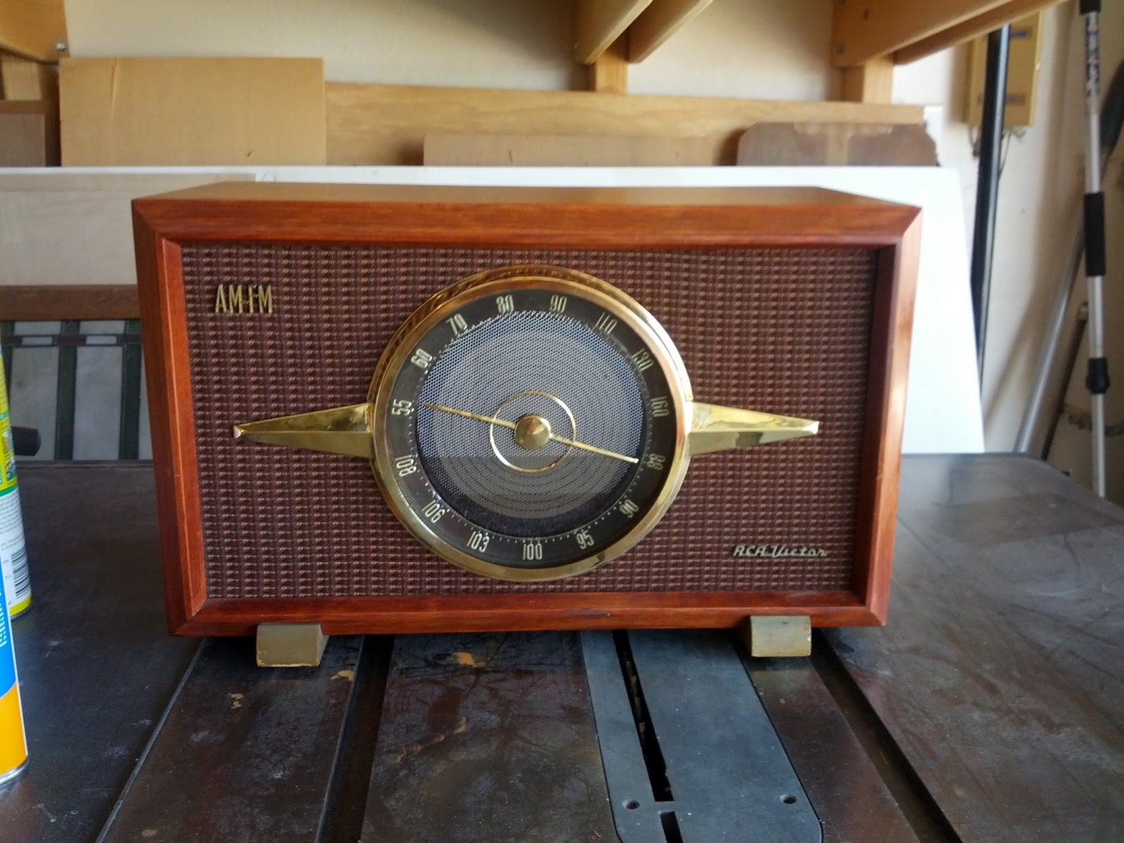
I've always found vintage electronics to be fascinating, particularly old radios. They built products with style back then, and completely by hand. I picked up this RCA Victor 6-RF-9 radio on craigslist the other day for only $20, it's a 1950s era AM/FM 9 tube radio. It was already in great condition externally, but cleaning up the case and polishing the brass has really made it look great. I am working on getting some capacitors to replace all the old perished electrolytic and waxed paper capacitors inside, and it will hopefully be in working order after that! Pictured is the housing after cleaning and polishing, the actual radio chassis is on the workbench waiting for parts.